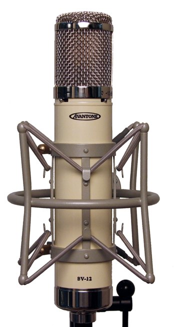
The Avantone BV-12
Continued...
Fixing the Dread Cathode Follower
I can hear you all thinking "Rip that Cathode Follower out by the roots!"
Well we can't.
The shiny little nickel alloy transformer in this mic has a ratio of 5:1. Gives you a hot output but you need to drive it with a low impedance source. The 1st stage plate follower in this mic. has an output impedance of 20,000 ohms. Not low enough by a long shot. We would need to replace the transformer with a 12:1 unit to match that tube.
The cathode follower circuit with a 6072 triode has an output impedance of about 550 ohms! Amazing isn't it? So we need to keep it, but it needs to be built correctly.
The correct way to build a cathode follower is to provide a proper bias voltage just like we do for any tube amplifier. With the bias voltage correctly set the tube "idles" (ticks over in Britain) at a healthy current value that can go up or down as the signal requires, without exceeding the tube's capacity.
It turns out that it takes only ONE EXTRA RESISTOR to do it properly. Here is the corrected circuit called the "Bootstrapped Cathode Follower".
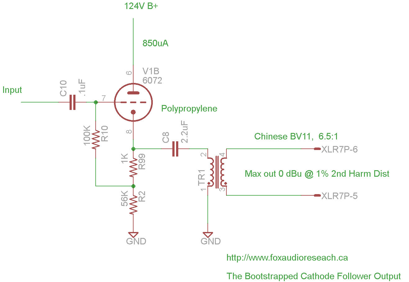
We added R99 which sets the bias voltage between the grid and the cathode and we reconnected R10 to the new position on R2.
Some people are going to say "Hey, you blew it with that input resistor R10. It's only 100K. That will load down the 1st stage amplifier too much." Normally that would be true if R10 was connected to ground, but due to the magic of negative feedback in the CF, that resistor appears to be much higher impedance depending on the amplication of the tube. An simple way to understand it is to think about the fact that the 100K resistor has the almost the same signal on it at both ends, because it's connected to the input and the output. So very little current flows through it. This makes it look more like a 1M ohm resistor to a driving circuit. It was important to keep the value of the impedance in that range so the High-Pass filter worked as expected. Even still we did have to reduce the size of the High pass capacitor by 1/2.
So notice this drawing says:
"Max out 0 dBu @ 1% 2nd Harmonic distortion"
(We use 1% as the limit for output like Neumann did for tube mics)
Compare that to the original circuit which was only capable of -9 dBu @ 3% distortion!!!
This circuit increases the headroom of the mic by 20dB or so.
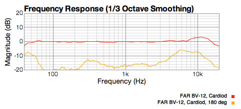
So with some EQ added back in the correct place, in the first stage, here is the distortion graph of the FAR BV-12. The old circuit was also stealing 2 dB of level from us. The new one puts out -7dB with the same -20 input.
This now meets our reference of less than 0.5% at 1KHz.
Since the owner of this mic has never heard his BV-12 we wanted to remain true to the BV-12 sound that we received. However we made a decision to use a little less EQ just to add a little extra sparkle to the mic; 1dB more lift to be exact. And believe me when I say, you can hear that 1dB. Microphones make or break on 1dB up or down when recording engineers and producers are listening.
Here is where we landed. It actually is very similar to the plots of the of original C12 and C24 microphones.
How Does it Sound?
By reducing the distortion on a tube microphone you take it from the realm of sub $500 mics and immediatley transform it into the realm of mics costing over $2,000. We find that after capsule quality, this single factor is what makes a mic sound great.
Now we know this is tube distortion and it is not as offensive as solid state distortion. In fact, for some tracks it is useful, almost like an exciter or distressor. However on vocals it creates a fuzzy, messy sound that you cannot correct with EQ or any other processing. So when people buy these mics for vocal recording, they are not always happy with the purchase.
I didn't make a recording of the sound when the BV-12 came in but I did one when it was fixed, because I quite like the sound of this mic now that it's cleaned up. I could have added more high end, but I wanted the customer to get a mic with the response of the original.
Summary
So the BV-12 was an attempt to create a better microphone and it succeeded partially. The mic response with the new capsule and the weird EQ method does make a very nice sounding mic from a response perspective. But the amount of distortion was completely un-acceptable for a professional microphone. This completely negated changing the transformer to the nickel alloy BV11, which should have lowered the distortion.
I did not mention that we also had to replace the tube, which is a no-name 6072 "made in Russia". It was 12 dB noisier than our Electro Harmonix tubes that we measure and select for low noise.
It makes me think that there is no desire to build new PC boards, but rather just to do the minimum to try and create a new sound. It's a shame. The BV-12 package is joy to look at. And with a little expertise, as we have shown, the sound can be made to match.
Now that we have done the research, we can improve your BV-12 too. Just send us a note: