The LA-610 Mk II
by Universal Audio

Simple improvements by Fox Audio Research
Updated July 5, 2012
We have been using an LA-610 in our home studio for a couple of years and although we peeked inside we had not taken the time to evaluate it in any way beyond how it sounded. Now make no mistake, the LA-610 is a good piece of gear right out of the box. It has a particular sound that I would best describe as "vintage". When I compare it to the very sterile sounding inputs of the Presonus Firestudio it has a very obvious sonic colour.
I should say at the outset that the Mk II uses an interesting mix of modern and old fashioned technology. Tube amplifier stages with transformer inputs and outputs are supported with modern switching power supplies and very tiny surface mount capacitors and resistors are peppered all over the printed circuit board. It's almost amusing to see blend of technologies, that extend over 60 years, all populating the same board.
I tried looking around for schematics for this box but it appears that Universal Audio has a strict no schematics in public policy. And it seems that they are enforcing it very effectively! So we had to look elsewhere.
The UA LA2A leveling amplifier is a vintage gain controlling amplifier that used an optical gain control element. The schematic for that unit is avialable online and after studying it, I took the approach that the compressor/limiter section of the LA-610 would be similar to the LA2A.
Well that's what assumptions get you. After feeling around inside with a voltmeter and tracing some signal paths I found that the output section of the LA-610 Mk II is COMPLETELY different than the LA2A!
Tube Functions
So without a schematic it's hard to figure out how the signal travels so I had to find another way. By simply removing tubes I was able to determine what each tube did! Here is what I found. (Tube numbers are from the PCB)
Preamp Tubes
- V1 - ECC83/12AX7 1/2 preamp, 1/2 EQ
- V4 - ECC81/12AT7 1/2 EQ, 1/2 Preamp section output stage
Compressor Tubes
- V2 - ECC81/12AT7 Compressor section output stage
- V3 - ECC83/12AX7 Compressor control preamp
- V5 - 6AQ5 flourescent opto unit driver
Another interesting thing is that in Bypass mode the only tubes that need to be plugged in are V1 and V4. This confirms that V1 is the preamp section and V4 must be the preamp output driver that connects directly to the output transformer!
After looking at the equalizer controls I can see that they work by applying feedback from V4 back to V1. So 1/2 of the 12AX7 and 1/2 of the 12AT7 are used to create the EQ.
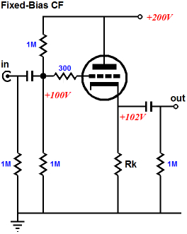
LA2A Output Elegance
The LA2A used a very elegant circuit call the White's Cathode Follower that features extremely low output impedance and is actually a "push-pull" output stage. This let's it pull current in both the positive and negative parts of the signal.
 >>>>
>>>>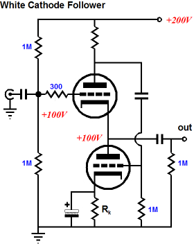
With the White's Cathode follower implemented with a 12BH7 dual triode tube the LA2A was capable of driving line levels at low distortion. Below are the LA2A Published specs for output:
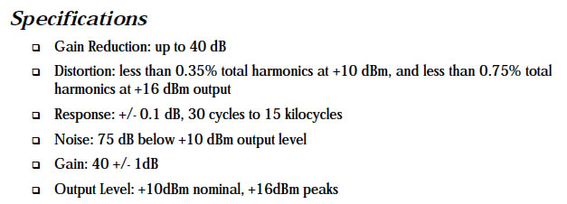
We can see it is capable of +16 dBm, meaning it was measured while driving a load, for audio 600 ohms was standard. At that level distortion is still at only 0.75%. We could project that at +18 dBm distortion would hit 1%. They don't mention if that is at all frequencies so we will assume it is true at 1 KHz.
LA-610 is Not the Same
The LA-610 MK II output section for both the Preamp and the Compresor are just a normal triode Plate followers. And they are using ECC81/12AT7 preamp tubes. Not really line driver tubes.
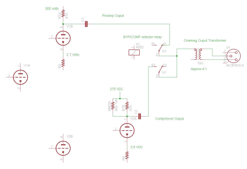
Below is a simplified view of what I think the output looks like in general. The Upper tube is V4, the preamp output and the Lower tube is V3, the compressor output. In this sketch, resistor R76 has been modified by adding a 56K ohm 1W resistor in parallel with the existing plate load resistor. More about that later...
How Does LA-610 Stack Up?
When we started testing we had no output load on the LA-610. It was plugged into the 1M ohm 1/4" inputs of my Firestudio box.
Something made me check the manual for the LA-610 and it said:
"Maximum output level ....... +23dBm
"Recommended minimum load ...... 600 ohms"
Note: The LA610 manual does not specify distortion for it's maximum level spec so it is not really meaningful.
So we did the testing with a 600 ohm load on the output. Guess what? Complete failure.
The LA-610 cannot make it's specified maximum output of +23 dBm into 600 ohms! It cannot even do it into 1500 ohms.
Below are the Output Specs we measured so you can compare them to the LA2A
- Distortion: less than 0.1% at +5dBm and less than 5% at +15dBm !!! (and that's only at 1KHz)
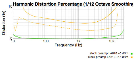 Notice how the distortion goes to over 5% when loaded with 600 ohms on the output and a level of 15dBm? (dBm measurements mean we are measuring power output in milli-watts)
So the LA-610 MK II is not designed to work into a 600 ohm input clearly. It must be connected to high impedance input to get any kind of useful audio quality. Those little preamp tubes as plate followers cannot act as real line drivers.
And remember this is the preamp section output only. There is NO COMPRESSOR in these measurements.
From here on we used a 1500 ohm load like the unit would see if you plug it into the XLR input of a modern audio to digital convertor.
Most digital inputs people used will have an input impedance of 1500 ohms or so for the XLR inputs so I tried a 1500 load and the LA-610 liked that a lot more!
Can we make it better?
The one thing that I noticed about the LA2A output stage is that it used a 12BH7 tube.
The 12BH7 is a low gain (16.5 times) dual triode that is capable of handling about 3.5 Watts of power in each triode. This tube is marked as discontinued in my RCA Tube Manual in 1961!
The good news is there is a very close relative still in use today! The 12AU7 / ECC82 has an amplication factor of 17 times and it can handle 2.5 Watts per triode.
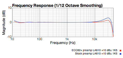
So what happens when we replace the stock V4 12AT7/ECC81 with an ECC82. Well we immediately get a flatter response. In fact a common complaint about the LA 610 Mk II, is that it sounds brighter that the original preamps built by Bill Putnam. So there's one small improvement.
Changing the preamp output stage also seems to reduce the distortion significantly too. At low levels and especially at high levels! (can you spell "more headroom")
LA-610 Specifications with the ECC82/12AU7 Output tube:
Distortion: less than 0.1% at +10dBu and less than 0.6% at +15dBu with a load of 1500 ohms.
Hmm... 0.6% at +15dBu... that is getting much closer to the LA2A!
In fact with the 12AU7/ ECC82 tube the preamp section generated +20dBu signal level into 1500 ohms with ONLY 1% 2nd Harmonic distortion. Versus WAY over 5% with the stock tube.
See the graphs below done at a few different levels.
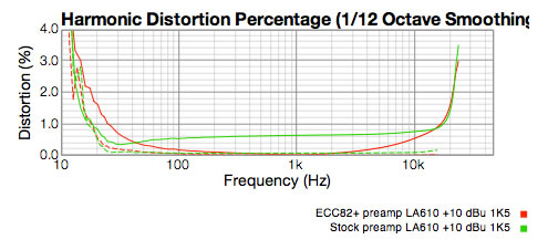
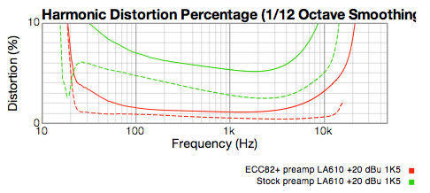
The ECC82 output tube is just touching 1% 2nd Harmonic distortion @ 1Khz in the +20 dBU graph. Notice that the scale is changed to 10%. This is so we can show the Stock 610 has over 5% distortion at 1KHz!
Since the VU meter on the LA 610 is calibrated such that 0VU = +4dBu and as we see in the graphs the LA-610 hits 1% distortion at +15dBu, when you load it with 1.5K ohms... There is barely 11dB of headroom above 0 Vu !!Keep the meter below 0VU as much as possible when using "stock" (un-modified) LA-610 MK II |
Preamp Linearity: Stock 12AT7 vs 12AU7
Test Method
- Set the signal injection level to -25 dBu
- Plugged the signal into the Microphone input
- Set the GAIN control to -10
- Set the MODE switch to BYP to bypass the compressor
- Adjust LEVEL knob to make 0 dBu output measure at the output connector
- For each test, turn the GAIN control on the LA-610 up 5 dB
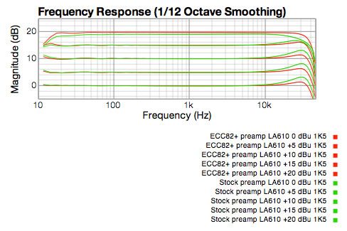
Notice how the stock preamp(green line) rolls off the high frequencies at +20 dBu output level, but the ECC82/12AU7 keeps going out to almost 30KHz.
What about the Compressor Section?
It turns out we get similar improvements if we change the compressor output section tube to an ECC82 as well. The frequency response smooths out at the high making the unit sound warmer. The distortion results are the same or slightly better at low levels but when you need the headroom the ECC82 performs WAY better. This supports my assumption that the output put circuits for the Preamp and the Compressor sections are the same or similar.
The big difference is that for some reason the preamp has 300 volts on the plate but the compressor only has 250 volts. This reduces the compressor's output power a little.
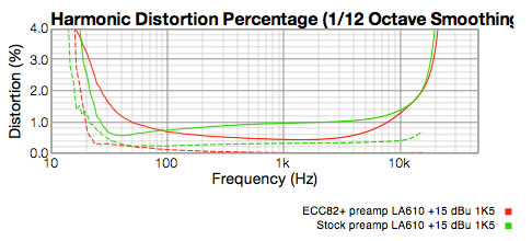
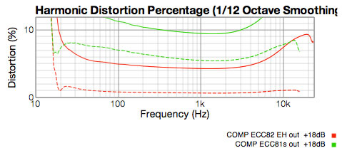
See below at +18dBu into 1500 ohms, the un-modified unit with the ECC81 tube has totally lost it.
10% 2nd Harmonic distortion is extremely bad even for tubes. And 5.5% 3rd Harmonic distortion; that is the really nasty sounding kind.
Notice the 3rd Harmonic is still below 1% for the modified LA610 (red lines) with the ECC82 at the same output level! That's one of the main reasons why it sounds better.
One more Recommended Mod
As we measured the V3 tube, the compressor output section, we found the tube was biased harder and the tube was not conducting as hard as the PREAMP section. We were getting higher distortion than the PREAMP output!. That's kind of weird. We found that the PREAMP ouput had a 300 volt plate supply, but the compressor had only 245 volts.
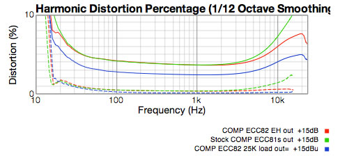
We changed the plate resistor on this tube by adding a 56K ohm resistor in parallel with the the 47K ohm resistor on the board. This creates a 25K ohm plate load resistor and it brought the current up to just over 4mA and reduced the distortion even more as you can see below.
With this mod and the ECC82/12AU7 the Compressor section performs about as well as the PREAMP section.
You can see below that at +15 dBu, just changing the Compressor output tube only improves distortion above 4KHz. But changing the plate resistor really reduces 2nd Harmonic distortion and it reduces the high end 3rd Harmonic distortion, which really cleans up the sound.
Not all tubes are Equal
I should warn you that I did get some bad results from some ECC82/12AU7 tubes. This caused me to go back and re-check everything. It turns out the Electro Harmonic ECC82 performs better in this role than the Tung-Sol version.
So how does it sound?
To my ear the LA-610 sounds more natural with the output tubes replaced. It actually now sounds like a piece of professional gear to me. That's best I can say about it. The differences are not enormous but it's cleaner and warmer. I hope your mileage is the same.
What you need:
Go to your favourite source of tubes and purchase two (2) high quality 12AU7 tubes. These are also called ECC82 or 6189 tubes.I put Electro Harmonix tubes in my LA-610, which in my batch performed better than the Tung-Sol versions.
What to Do:
If you decide to open your LA610 as described below, you are exposing yourself to potentially lethal electric shock. If you attempt any soldering on the board you run the risk of damaging the board which could require replacing the entire board. We recommend that only experienced and qualified technicians work inside vacuum tube (valve) equipment. Furthermore Brian Fox disclaims any and all liability of incidental, special or consequential damages arising from your modification of your equipment or the subsequent inoperability of your equipment after your work is completed. |
Warning! Electric shock HAZARD potential
UN-PLUG your LA-610 from the power outlet and wait for a FULL two minutes for all the power supply voltages to decay.
Modification 1: Replace compressor output tube
- Using a Philipps screw driver remove the top cover of your LA-610 Mk II so you see something like the picture below. ( put each screw from the cover in a little bowl to protect them from the screw monster)
- Look at the printed circuit board and find the the tube number V2 (3rd from the left in the photo below)
- Primary MOD: replace stock V2 with your ECC82 tube
(You can stop right here if you want and it's still better than stock)
Modification 2: (Optional) Replace PREAMP output tube
- Look at the printed circuit board and find the the tube number V4 (2nd from the left in the photo below)
- Replace stock V4 replace them with the ECC82/12AU7
Note: this will reduce the maximum PREAMP gain by 2.5dB. Not a big deal but I thought you should know.
Modification 3: ***VOIDS the warranty***
1. Find *R76 on the PCB. 47K, 5% , 1/2 Watt resistor. It is beside V2.
*Special thanks to Mark Scheuer who pointed out that it is R76. I had a typo in this article for quite a while
2. Take a 56K ohm, 1W resistor and solder it in parallel across R76
This increases the current through the output tube, lowers distortion to be equal to the BYPASS mode distortion and flattens the response above 10Khz.
Button it Up
- Carefully place the cover plate back on the LA-610, replace all the screws
- Plug in your compressor and enjoy the improved sound!
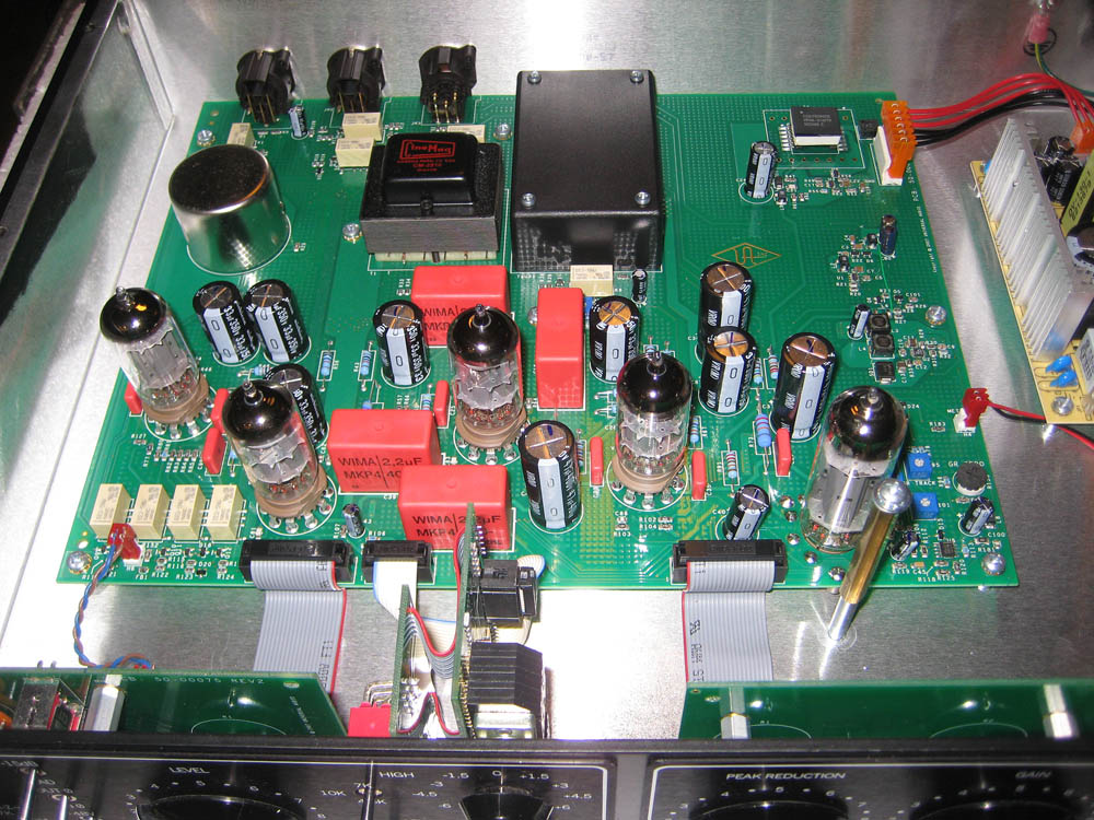
Tubes from left to right: V1 , V4, V2, V3, V5
If you have any comments for us on this article send them to :
Product Reviews Disclaimer