The VF14
...continued from page 1
![]()
Enter the *Telefunken VF14K
After installing a proper bleeder resistor I knew I needed to get a replacement tube to really rule out anything else as the cause of the noise. A vintage tube was out of my snack bracket, but what about a VF14K? It was said to be pin for pin compatible. After a few email exchanges there was one on its way thanks to Alan Venitosh at T-Funk.
So the sad part of the story is that the VF14K proved beyond a shadow of a doubt that the old tube was faulty. R.I.P vintage tube. The VF14K went into the vintage circuit and just worked. No noise, no problems. It just worked. And it sounded very good too.
(Relax. There are some sound samples coming)
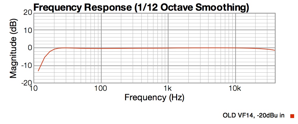
I was curious if I could measure any differences in response or distortion. Below is a graph of the original VF14 circuit response with the supply adjusted so the voltages were as close to nominal as I could get them. This test is made by injecting a -20dBu signal, from low impedance source, directly into the mic. circuit input and plotting the output. This test is mostly letting us see the output capabilities of the tube/transformer combination.
Note: For the curious the preamp load (impedance) is 1,500 ohms
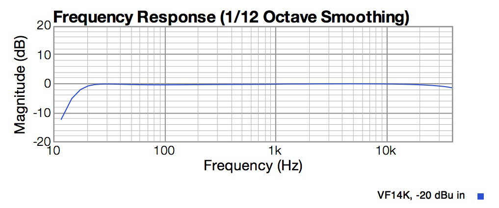
You can see that there is no difference in the frequency response of the preamp circuit with the old VF14 and the new VF14K. Also notice how excellent the response of this old design is. By the way the gentle roll-off about 20,000Hz is caused by this particular BV8 transformer. Other BV8s can be flat out 40,000 and some have slightly more roll-off.
Next let’s look at the 2nd and 3rd harmonic distortion. There is very little difference here as well.
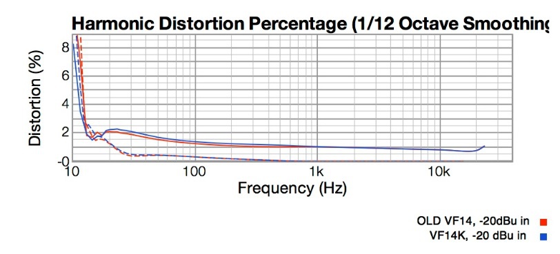
And remember the VF14K is putting out 3.3 dB more signal than the old tube. That means more than double the power output in electrical terms which is a big deal for a tube circuit.
The specification from Telefunken is that the VF14K has 2dB more gain than the old VF14, so that means our old tube was going soft in the gain department by 1.3 dB. Since It’s been 60 years since WWII that’s not bad!
Looks like the Telefunken VF14K is pretty darn to close to the real deal electrically. I know what you are thinking. I can hear it at my desk while I am writing this.
HOW DID IT SOUND? !!
To be honest there was a slight difference in the sound. And I would not be honest if I did not tell you that I could find reasons to prefer the vintage tube, well at least until it would start making noise. There was some kind of open-ness to the old VF14 that the modern one didn’t quite have but it was helluva close. Truth be told if you tracked with one tube or the other, the difference would not register on the finished product. I really believe that.
In the end, my client opted to go with his EF802. We used a new power supply that I customized for him. He knew he could replace the EF802s easily and at a good price. And I know the original power supply made him a little uneasy after what we discovered.
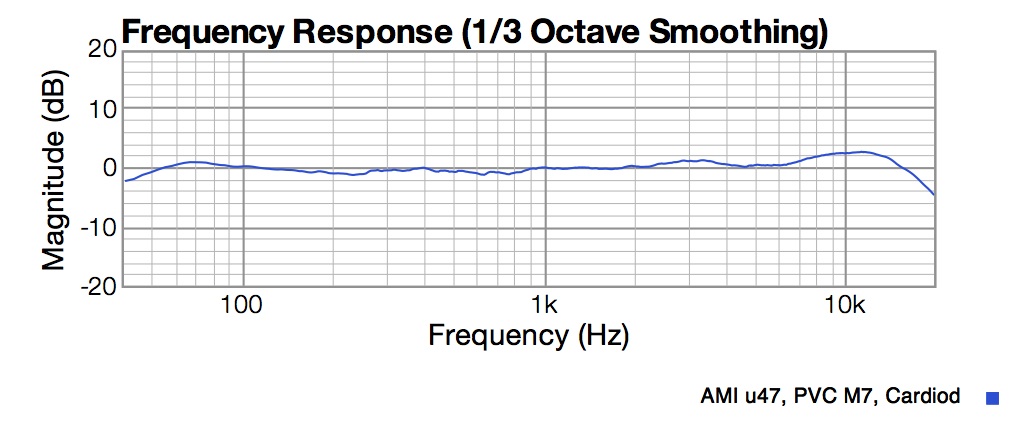
And remember that missing low end? Turns out that the capsule was the problem as you can see in the graph below.
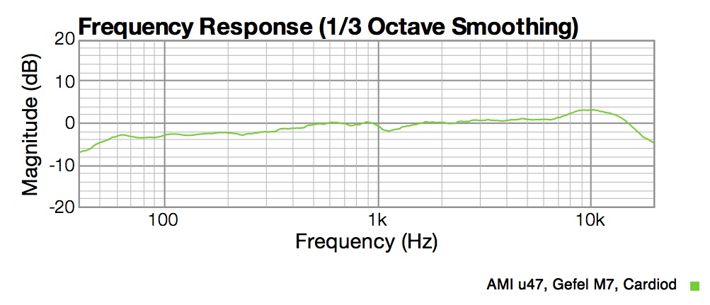
Plugging the mic. into a hot supply would have applied about 300 Volts to capsule for a short period of time! Did those high voltage hits cause this low end failure? I can’t be certain but it's possible.
But I know when I put in a new German made m7, it looked like this and that’s the kind of low end I expect from a u47.
WAV Sound Samples
Each of these sound samples were made with the same German made m7 PVC skinned capsule. In the first two samples all that varied was the VF14 tube and the VF14K tube.
In third example the circuit changes and uses the EF802 tube and modern style supply with separate filament and B+ voltages. Bias is created using our dual diode fixed bias voltage technique.
Disclaimer: Please reserve judgment on these recordings. I made them on different days and my voice and energy levels vary quite a bit from one to the other. There are also some differences in my distance from the mic which changes the proximity effect (low end) a bit. I tried to set the levels close but no compression or limiting is used to enforce it.
AMI u47 with OLD VF14
AMI u47 with NEW VF14K
FAR Modified AMI u47 with EF802 and new Supply
Conclusions
So would I use a VF14K in my vintage u47? Absolutely!
It’s plugin ready to go and will sound better than most of the VF14 tubes you will find left to use from the 1940s. When I compare it to the EF802 I couldn’t really hear a difference that I would call critical to making a good recording. As most of my research has indicated, the capsule sets the primary "sound" of the mic. The electronics adds more subtle effects that you may or may not like.
So if you have a vintage u47 or an accurate clone, You can sleep at night knowing that when Kanye shows up at your studio to use your u47, Telefunken has your back if your old VF14 tube goes down mid-session.
Disclaimer
Telefunken Elektroakustik agreed to provide us with a new VF14K tube for these tests with the understanding that we would write a report on what we found. Our agreement was that Fox Audio Research would retain full editorial control over the content. Telefunken reviewed the content of the article prior to publication to approve correct use of their trademarks. No funds were exchanged and the VF14K tube will be returned to Telefunken USA shortly with thanks.
Contact us at: