Making An 800 Clone
Brian Fox, May 28, 2016
A customer recently mentioned to me that they had a friend who wondered if I could build anything that sounded like a Sony c800 ™. I said I have never really looked closely at the microphone and that I would get back to them. That is one expensive microphone with prices running over $8,999.00 US dollars. That's like a million Canadian dollars up here in the great white north!
Thankfully the internet provided no end of schematics and reviews so it was pretty simple to get a good overview of the c800. The first thing I will do is review the microphone technically so we can see what we are up against to try and clone this black monster.
An over-riding tone to the comments on the net point to some reliability issues with the microphone and extremely short tube life. I attribute all of these comments to a poor tube choice by Sony and the fact that they use three of these troublesome bottles.
Many of the comments favour the sound of the microphone and give big cred to the “clarity” and “detail” in the sound. This is very consistent with the use of a K67 capsule in an un-equalized microphone impedance converter circuit. The rising response of the K67 builds presence boost right into the sound. Couple the presence boost with a high voltage triode and you get the ability to pass all that boosted treble out the business end with amazing clarity and just a touch of musical 2nd harmonic “silk” on top.
Out of the gate the microphone has a number of unusual technical features that jump out at me because they are not common in some of the classic tube microphones. I will list them and then give a commentary on how important they are to replicate the c800 sound in a different microphone.
- 6AU6 pentode (EF90) in the audio chain
- Vacuum tube (6AU6) rectifier tubes
- High anode voltage (230 volts)
- High tube current (1.4mA)
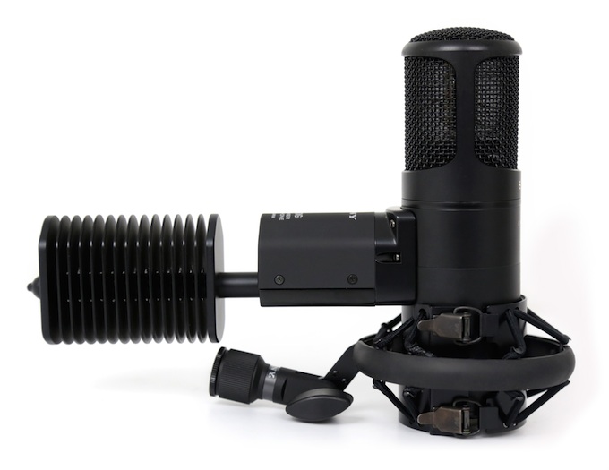
- Pelletier cooling device
- Large output transformer (9:1)
- K67 style capsule (but with slightly different response than Neumann)
- U47 style capsule connection to the tube
- High current voltage divider for capsule
- Large internal de-coupling capacitor
These ten features of the c800 set it apart from other tube microphones including most of the mics that I make so let’s take them apart and see what they mean.
6AU6/EF94 Tube
I am dating myself I know but heck I am a grandfather now so I am good with it. My point is that I have a clear memory of removing a 6AU6 tube from my mother’s cheap table top radio in the 1960s. This was a radio that was essentially a throw away device in its day. The 6AU6 is not a very notable tube and from reviews I read on the c800 it has trouble with microphonics and noise. That does not mean you cannot find a 6AU6 that is fit for a microphone, but you may have to sift through a bunch of them and you may not be able to expect the kind of reliability you see from other tubes. In case it’s not clear, I disagree with the choice.
Why would Sony choose this tube? I cannot be certain, but there might be some “woo-woo” beliefs going on that since the u47 and the u67 used a Pentode wired as a triode, the safe money was saying use a Pentode! The one redeeming specification I can see for the 6AU6 is that when wired as a triode it gives the designer a very low plate resistance, which translates into a low output impedance which in turn means it can drive a transformer with a higher ratio. This means higher output level from the microphone which is good to keep the signal to noise ratio high. But honestly other than that I can think of no reason to choose this tube for a microphone.
6AU6 Rectifiers?
That brings us to the two, count them, two 6AU6 tubes in the c800 power supply. Why? The marketing department claims this provides a slow power ramp up to the microphone, which is true, but the same thing can be accomplished by using a resistors and large capacitors in the filter circuit. And the R/C method is far more reliable. And furthermore the 6AU6 is a pentode, not a diode and tube diodes are what you used as rectifiers if you want a tube power supply. However some studios have found that when the tube in the mic. goes bad, which it seems to do frequently, they just swap it with one in the power supply and the session keeps going so maybe there is a little method to the Sony madness.
At the end of the day, there is no good reason to use vacuum tube rectification in a microphone. Guitar amps can use them to create a unique distortionsound due to the voltage dropping on high power output. This makes sense. But a microphone draws the same current ALL THE TIME!. Silicon diodes work just fine thank you.
High Anode Voltage
The benchmark tube microphone that started all this technology was of course the u47 and it had its own set of peculiarities. My take has always been the VF14 tube was chosen so that Neumann did not have to build a high current filament supply in the microphone. Whether I am right or not, the outcome of the decision to use the VF14 meant that the u47 had a pretty low anode voltage in order to be used as afilament voltage as well. For the record the u47 used was 110 Volts for the Anode supply and used a resistor to drop the voltage to 35 Volts for the tube filament.
Running a tube at lower voltages means you reduce the maximum voltage swing that the tube can generate and therefore reduce the headroom. You also tend to reduce the gain of the tube stage a little.
So by essentially doubling the voltage Sony ™ gave the C800 the potential for 6dB more output than the same microphone running at 115 Volts. A good call for a modern tube microphone in the digital audio age.
High Tube Current
By choosing high voltage Sony ™ gave their microphone the ability to generate about 6dB more signal (double the output voltage). This a great thing for clarity in a tube a circuit. At normal levels, the microphone is just coasting, but when you really hit it, it has the goods to deliver. The negative side effect is that because they chose a tube with a low plate resistance the current goes up quite a bit a with 230 volts applied. So where a u47 or m251 will conduct about 0.5 mA of current the c800 is conducting almost three times as much. (1.4mA) This may not seem like a lot but it is important to remember that the tube sees the total power, which is the current times the voltage. That power in a Class A amplifier circuit is mostly dissipated as heat. This leads us to how do you keep the c800 microphone from overheating.
Pelletier Cooling Device
This one feature is the most unique component of the c800. A Pelletier cooling device uses a feature of bi-metallic junctions that allows them to extract heat when a little electricity flows throw the junction. It is in a sense a solid-state refrigerator.
Why does a single tube circuit in a microphone need such a thing? I have no idea. The marketing materials indicate that keeping the tube cool lowers the noise by 1 or 2 dB. But the truth is that the tube is only dealing with:
100V (across the tube) X .0014A = 0.14 Watts!
The tube can handle 1W maximum so it is clearly in a safe place for power dissipation.
I would say pick a better tube and loose the cooling device so that’s what we did.
If a microphone in the c800 style interests you send us a note to request a quote at: