More Transformer Talk
Which transformer do I choose and why?
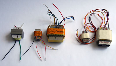
Left to right, some of da boys!
APEX, Peluso BV11P, BV8HR, Cinemag CM-2480, CM-2461NiCo
I thought I would take a minute to write a few thoughts on how to a choose a microphone transformer and how they work, in words that make sense to the recordist and do it yourself mic. modder.
So why do we even need a transformer in a microphone?
In fact microphones don't need a transformer, but it is still common to have one in professional microphones. Typically older high impedance microphones have been built that have no transformer. And nowadays it is cheaper to build low impedance solid-state output circuits to provide balanced output for microphones.
But the transformer in a high quality microphone has two primary jobs:
- Perform an impedance transformation of the high impedance signal coming from the tube or transistor amplifier in the microphone, to the low impedance signal required for today's studio microphone preamps.
- Balance the output signal above ground. This means that both wires of the microphone's output are not touching ground. This is sometimes called a floating output and it has advantages we will briefly describe.
The choice of which transformer to use depends on the characteristics of the little preamp in the mic and what it has to connect to in the outside world.
Impedance Transformation
What is impedance and why should we care. It's probably easiest to understand impedance if we think about it in terms of something more tangible, like a water system.
A high impedance water system is a 1/8" copper tube with water pressure at 150 pounds per square inch (PSI)
A low impedance water system is a 12" pipe with 5 PSI of pressure.
See the difference?
Which pipe has more pressure?
But which pipe could fill up your swimming pool the fastest?
So it is with electrical/electronic circuits. Voltage is electrical pressure. Current is the volume of electrons flowing through the wire. (like the volume of water molecules in a pipe) The combination of the circuits ability to deliver both of these electrical quantities determine its impedance.
The little amplifier in your microphone is like the 1/8" copper tube, especially if it's a tube amplifier. It may have over 100 volts of "pressure" but it can't push too many electrons at one time.
What's the cure? A transformer!
A transformer takes AC (and only AC) voltage into a coil and that voltage (pressure) pushes electrons through the wire of the coil and that, in turn, creates a *moving magnetic field.
*Important to note this is a "moving" magnetic field. A static magnetic field cannot do what comes next!
If you place a second coil of wire in that moving magnetic field, by placing it near the first coil, you will get the same signal on the ends of the wires of that second coil as you put into the first coil! This is due to "coupling" of the two coils by the magnetic field.
You can improve the "coupling" of the two coils by using iron to hold all (or most) of the magnetic field close to the to coils. The iron acts to a magnetic field like wire does for electricity. It directs it to places. This is a simple way to think of it but suffices for our explanation.
Here is where the magic transformation happens. If both coils have the same number of turns then what goes in... comes back out the other coil. (minus any losses dues to imperfections in how the transformer is built)
If you have 2 times more coils on the input coil than you have on the output coil or what's called a 2:1 turns ratio, then the voltage coming out of the second coil is 1/2 of the input, but can move 2 times more current! That's an impedance transformation.
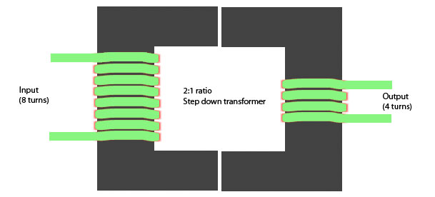 Simple step down transformer example with iron core (black)
in reality many more turns are needed.
Ok, so what does that mean for my microphone?
So it turns out that most microphone preamps these days have an input impedance of about 1,500 ohms. For simplicity that is like saying the mic preamp puts a 1,500 ohm resistor across the output wires of the microphone. Why that is so is a history lesson and I won't go into it here. Just take it as fact for now.
In order for that 1,500 ohms to have little effect on the sound quality of the mic, the mic must have an output impedance 10 times lower than that or 150 ohms. Ahhhh... that's where that number comes from.
Transformers have a cool property that whatever impedance is on one coil, it automatically is reflected through onto the other coil. So if the transformer has a 1:1 "turns ratio" and you put 1,500 ohms on the output side, it looks pretty much like 1,500 ohms on the input side. Cool huh?
But here is the weird part. Due to the physics of electricity when the transformer is NOT 1:1 things change big time!
If the transformer has a 10:1 turns ratio the impedance one side is reflected not at 10:1 ratio, like you would expect, but at a 10 x 10 to 1 ratio! That's right the IMPEDANCE ratio is the turns ratio SQUARED.
(read that again so you really get it) :-)
This means that if you use a 10:1 transformer in your tube mic., and the preamp you use in your studio for tracking has a 1,500 ohm input impedance then the tube will be seeing the equivalent of:
1,500 X (10 x 10) = 150,000 ohms
... at the tube side of the transformer.
But guess what? That is more like what the plate follower tube preamp circuit inside the mic needs to see. Why? Because the output impedance of the plate follower tube circuit is very high.
For a 12AX7 it is on the order of 38,000 ohms. For a 6072 it is 20,000. For a 12AT7 tube it is about 10,000, all other things being equal.
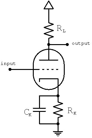
Every Plate follower circuit like this one has an output impedance. This is determined primarily by the plate resistor RL and the tube type. Connecting a low impedance to the output is asking the circuit to deliver more current than it can actually produce. It will reduce the audio quality; give narrow frequency response and high distortion.
You can get amplifer output impedance info for typical preamp tubes right here
Here is the important point. The tube preamp in the mic is very delicate. It is a high impedance source. It is like the 1/8" copper tube. It can deliver high pressure but not a lot of quantity. In fact the general rule for anything connecting to a tube amp output is to make sure the "load" on the tube is at least 10 times more than the output impedance.
So in theory a 12AX7 tube amp should never be connected to a load lower than :
38,000 x 10 = 380,000 ohms
That's pretty high but if you use a transformer with a high ratio you can do it.
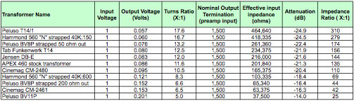
In the chart below I have listed a selection of transformers with the numbers you need to know to help match your tube mic's circuit to a transformer.
We can see for the 12AX7 example we would have to use a Peluso T14/1 or the Hammond 560 "n" to get a high enough impedance on input side of the transformer, although the BV8P might be useableif strapped for 50 ohms on the output coil. That transformation comes in at 261,000 ohms on the input side, if and only if you still keep the load in the preamp at 1,500 ohms! Remember what's on one side of the transformer shows up on the other side.
So you can see that you can play some games with the windings of the transformer by simply using the difference ratios. Like using the 50 ohm windings as if it was a 150 ohm winding.
And no this does not cause all the Angels in Heaven to run to the almighty and complain. It's perfectly legal in electrical terms.
 Pdf version Transformer Specs Table
Balanced Output
Professional audio is preferrably balanced. Balanced lines give great noise rejection. This is especially true when transformers are used for output and input. This is why a microphone with transformer output can typically used over very long mic cable.
Because of the transformer the signals from the mic are out of phase on each wire and the Studio preamp can only "pickup" signals that are out of phase because the input leads are also a transformer or the equivalent solid state circuit.
Any noise that gets on the signal wires is IN phase ( called common mode noise) and so when it hits the studio preamp input it cancels out to nothing inside the transformer.
Think about it:
if there is +1 volts of noise on pin 2 of the input, and +1 volts of noise on pin 3 of the input, the noise cannot make current flow through the coil, therefore no magnetic field due to noise in the transformer, therefore the output coil sees... nothing!
That's the magic of balanced lines. 100 years before digital audio, balanced lines allowed the creation of a telephone network that passed audio over tens of miles with virtually no AC hum!
And it was all done with transformers because active inputs don't have enough "common mode rejection" (now you know what that means) at low frequencies to do the job.

Balanced line illustration showing typical configuration. Signal is + and - (opposite phase) and so it creates a signal on the input transformer. Noise is in phase(common mode) on both lines and so is "rejected" by the "common mode rejection" of the transformer. *This even works without shielding on the wire!
No kidding.
Conclusion
Which transformer you choose for your microphone like all engineering decisions, depends on what you want to accomplish. It is important to understand what your mic's internal preamp tube is capable of. This gives you what you need to make the best choice.
If you have any questions send us a note at: