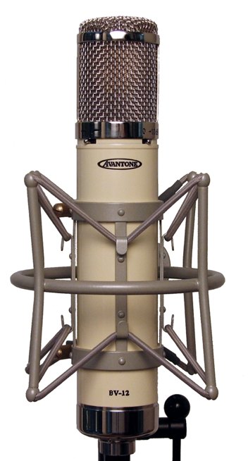
The Avantone BV-12
Continued...
So just on the off chance that C9 and C10 are causing this response, we removed them from the circuit board.
Then we put the mic back into the Faraday cage and we saw this response:
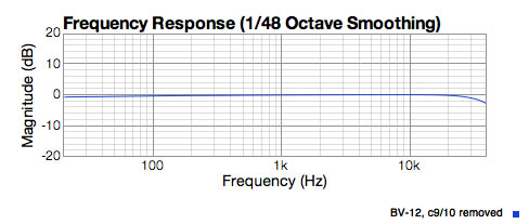
The small roll off above 20KHz is actually the filter in my Apogee Ensemble. That's correct, the Apogee is always -3dB at 40Khz no matter the sample rate! So in fact this mic is flat out past 40KHz.
So there it is. Those capacitors were pulling down the high end. No question about it. But that is the worst way to accomplish this goal. Look at what happens to the mic's distortion:
And yes that is over 20% distortion at 20KHz! Not pro audio quality. Not even close. And 3rd harmonic distortion is sitting at 3% at 8Khz and above. That's a very "crunchy" sound.
We also noticed that this new transformer is putting out about 5 dB more signal than old CV-12 or an APEX 460. With -20 dBu in the CV-12 puts out about -14dBu. The BV-12 is putting out -9.2 dBU. This makes it a very similar ratio to the Peluso BV11P transformer.
And what happens to the acoustic response with those capacitors removed?
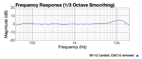
This is more like we see with the RK12 capsule. Although the high end lift is a little less. A good source has informed us that the BV-12 capsule uses a 6 micron diaphragm and whereas the RK12 uses a 3 micron skin. this could explain part of the difference.
So maybe we are all done with our analysis. Or maybe not.
Distortion Quest
With C9 and C10 removed we have seen the acoustic response return to normal. I just had to check the distortion now to confirm that it met my expectations. Boy was I surprised!
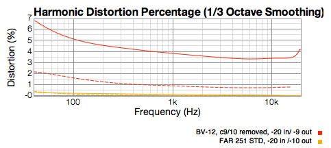
The distortion at 1KHz was the same as before, 4%. The high end went down but was still way too high and the low end actually went up. I took out my reference FAR 251 STD which uses the CCDA two triode 6072 circuit, just to be sure my measurement equipment was working right. You can see the results in the yellow lines above. The distortion for our mic is way less than 1% with the same levels. Now what's to blame in the BV-12 circuit?
I think I know the answer at this point. In the past with the CV-12 I also saw high distortion in the stock circuit and my solution was always to re-wire the mic to a CCDA circuit or to a replica c12 single triode circuit, depending on the customer's budget. (Replica circuit is a big re-wire so it costs a little more)
I happen to know that the Avantone circuit is a regular tube mic circuit, the plate follower, which is capacitor "coupled" to a "Simple Cathode Follower" output stage. The Simple Cathode follower is a cheap way to make an impedance convertor circuit but it is not optimal. It is VERY simple. One extra triode, an input cap, an input resistor, a cathode resistor and the output capacitor.
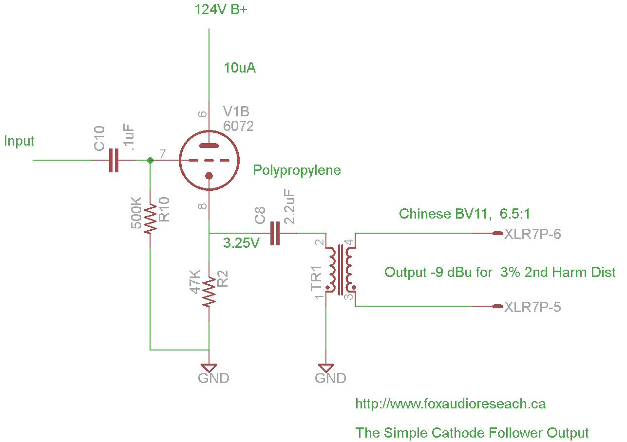
We have simplified the input in this drawing. The BV-12 and CV-12 have two input caps. 0.1 uF for wideband sound and a 2000pF one is selected to create the high pass filter.
A simple solution is to use a lower cathode resistor to increase the current through the tube. I swapped the 47K resistor for 22K and it did get a little better as you can see below. But it was nowhere near FAR standards. Non-musical 3rd Harmonix distortion (dotted line) should be almost non-existant at these levels and it was still sitting near 1%!
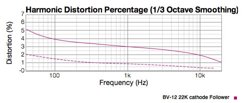 In this graph I have added correct EQ back into circuit so high end distortion drops from that.
I made a choice for this customer, that to preserve the intentions of the mic designer, I would fix this output stage rather than re-wire the circuit completely. The poor fellow had never heard this mic. I had been in the shop longer than it had been at his studio!
The Final chapter and the results are here
If you have any comments for us on this review send them to :